Describe the adapter plate between your robot and your tool in plain words. spec2cad returns a STEP file and a checked drawing, each proven against the robot's own flange before anything is machined.
Request trial access I have an access codeThe language model proposes. Code builds. An independent checker decides.
“Our vacuum gripper on a UR5e: 4 × M5 on a 40 mm circle, a 16 mm hole for the hose.”
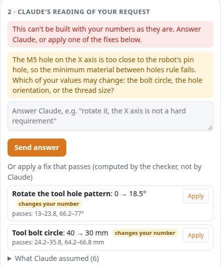
Claude writes a structured spec. Your numbers are frozen in code; if the request can't work, it says why and asks.
A deterministic generator builds the solid. The model never draws geometry.
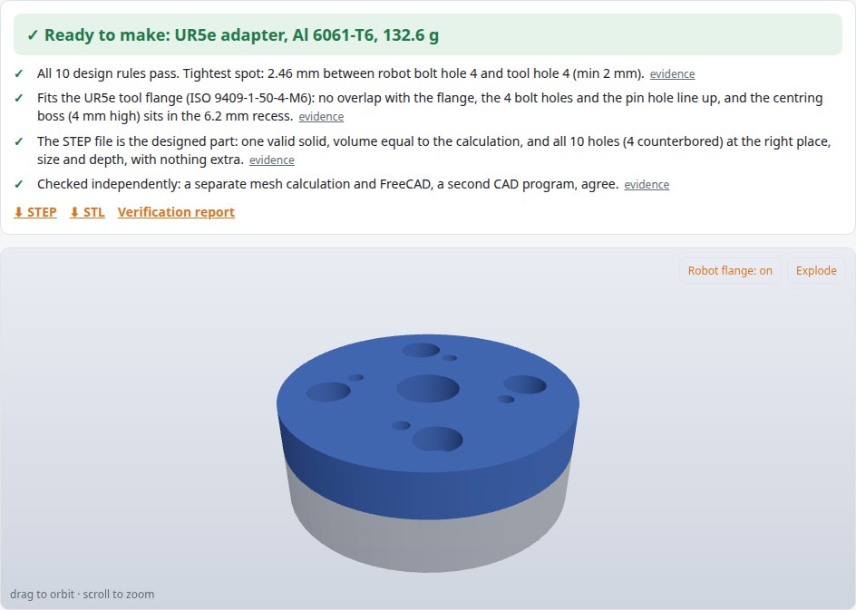
Every file and every dimension on the drawing is measured and checked against the plan and the robot's flange.
Put a gripper hole on the robot's X axis and it lands on the ISO 9409-1 locating pin. spec2cad stops before building, explains the conflict, and shows the changes that pass, computed by the checker, not guessed by the model.


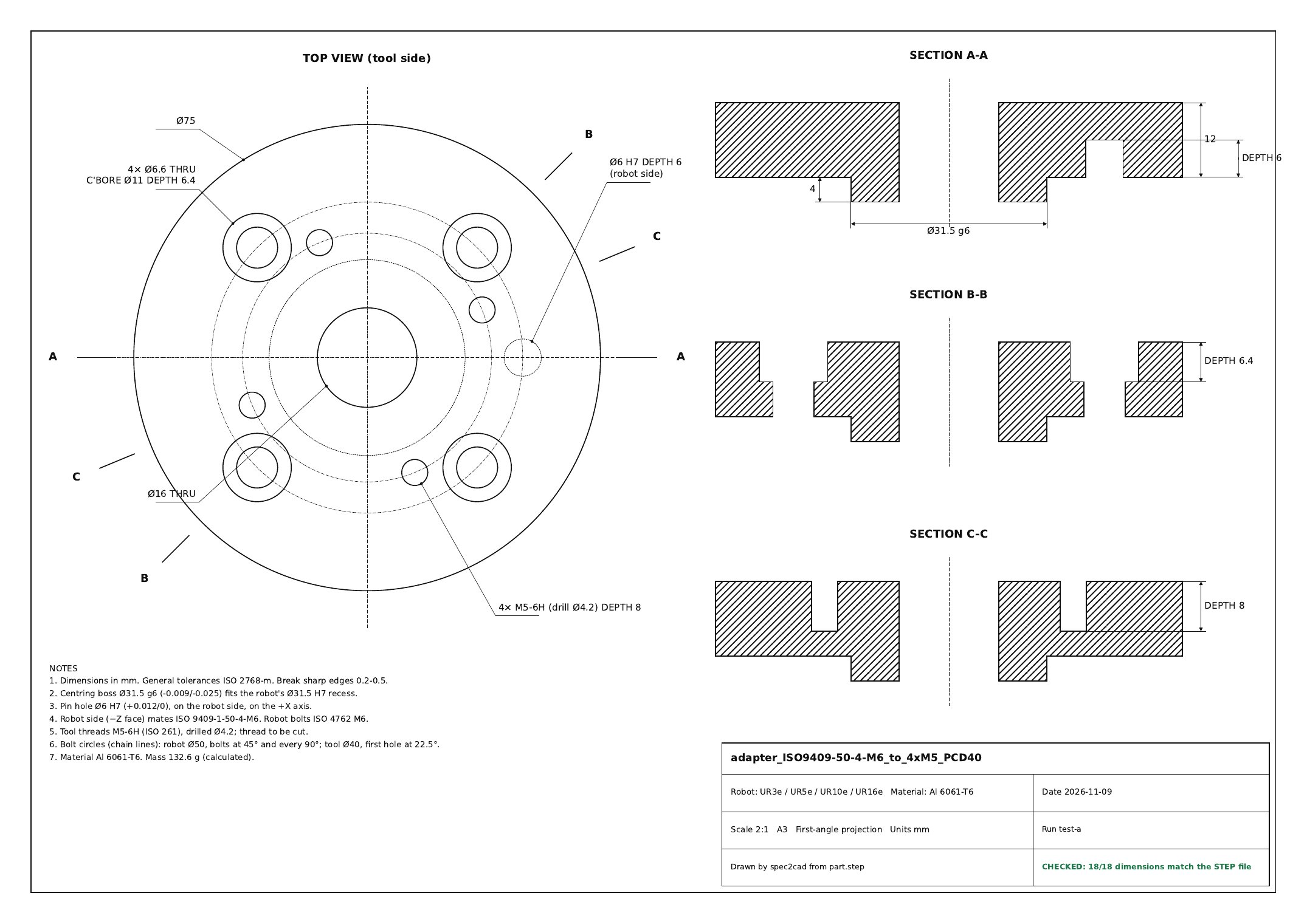
The views are projected and cut from the delivered solid. If a single dimension on the sheet does not match the file, the sheet is stamped NOT CHECKED and nothing is released.

Covered now: ISO 9409-1 adapter plates for the 50-4-M6 tool flange (UR3e, UR5e, UR10e, UR16e), in aluminium or stainless steel, with any tool bolt pattern of M3–M8 threads and an optional cable hole.
Next: more robot flanges, gripper fingers and brackets. We are choosing the order with the engineers in our trial; tell us what you design most often.
Note: flange dimensions are taken from the robot maker's published drawing and cited in every report. Tolerances and fits on the drawing follow ISO 286-2 and ISO 2768-m.